- Project Overview:
- This PCB design implements a compact XT60 inline current meter module powered by an ESP-01 microcontroller and the INA219 bi-directional current/power monitor. The board measures voltage and current from 5–26V DC, with a configurable sensing range up to 40A for high-power applications such as LED strips and RC batteries or even 3D Printers.
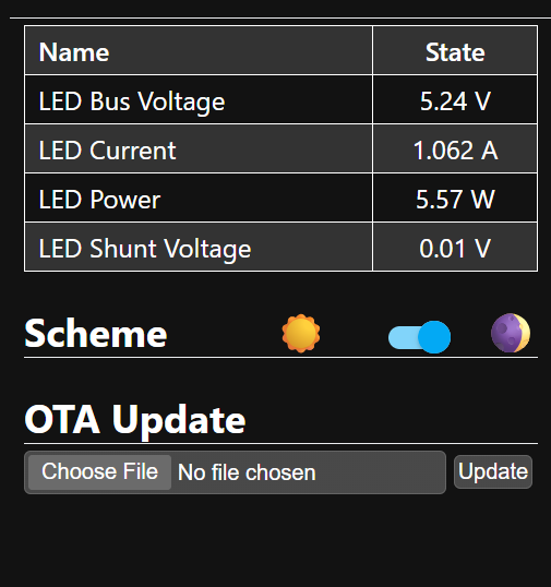
- It features full Home Assistant integration via ESPHome, delivering real-time telemetry of voltage, current, shunt voltage, and power, with OTA firmware update capability.
Design Details:
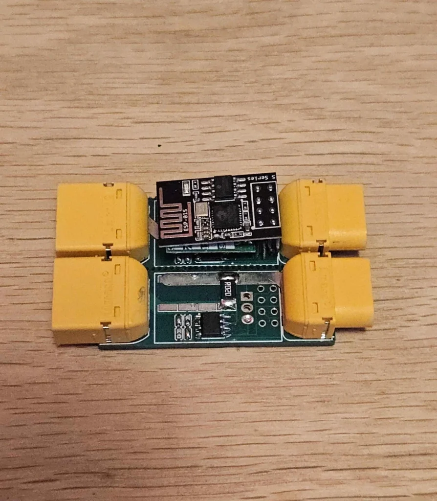
- XT60 In-Line PCB:
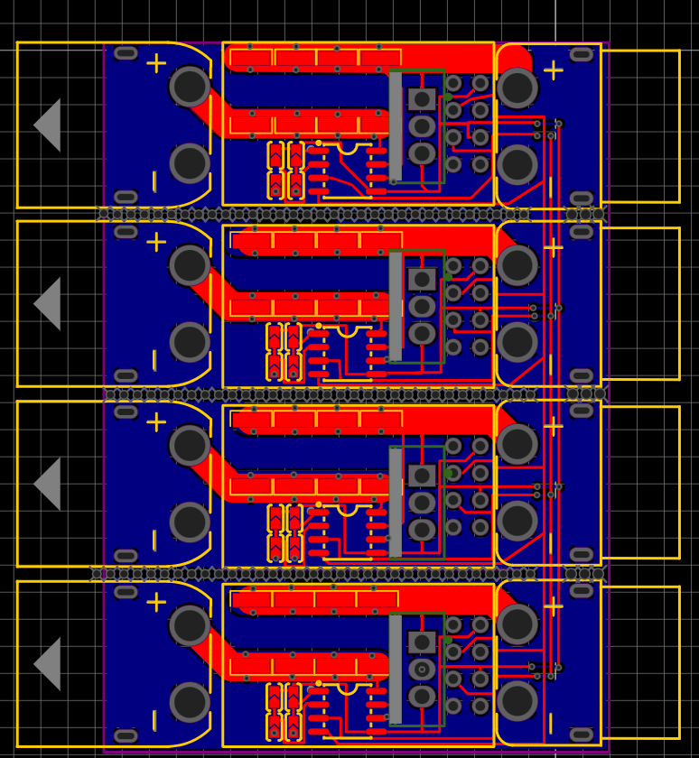
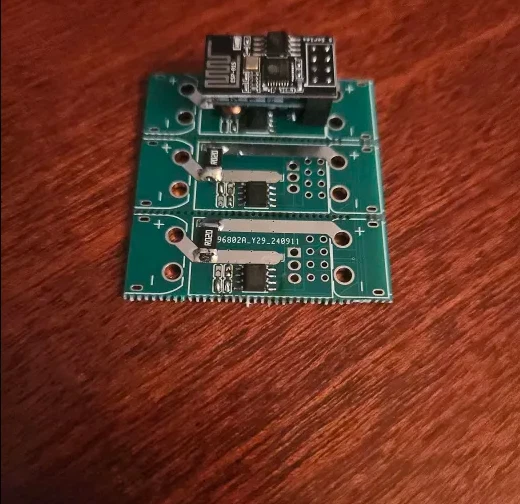
- The board is designed in a panelized layout for multi-channel assembly (up to 4 meters per PCB). Both the input and output are XT60 connectors, providing low-resistance, high-current connections.
- Wide copper pours and short traces minimize voltage drop and thermal loss even at high currents.
- Current & Voltage Sensing:
- INA219 monitors both bus voltage and shunt current using precision 20mΩ resistors (configurable for other shunt values). Up to four parallel channels are supported per board for multi-circuit monitoring.
- Jumper settings allow for easy configuration of sensing channels and measurement range.
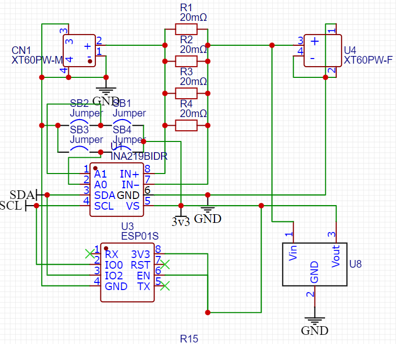
- Onboard Power Regulation:
- An integrated buck converter (U8) steps down input voltage (5–26V) to 3.3V for the ESP-01 and sensor ICs, ensuring stable operation across wide input ranges.
- MCU & Connectivity:
- The ESP-01S WiFi microcontroller hosts the ESPHome firmware and handles I2C communication with the INA219 sensors.
- All sensor values are published to Home Assistant, and the device supports OTA firmware upgrades for easy maintenance and updates.
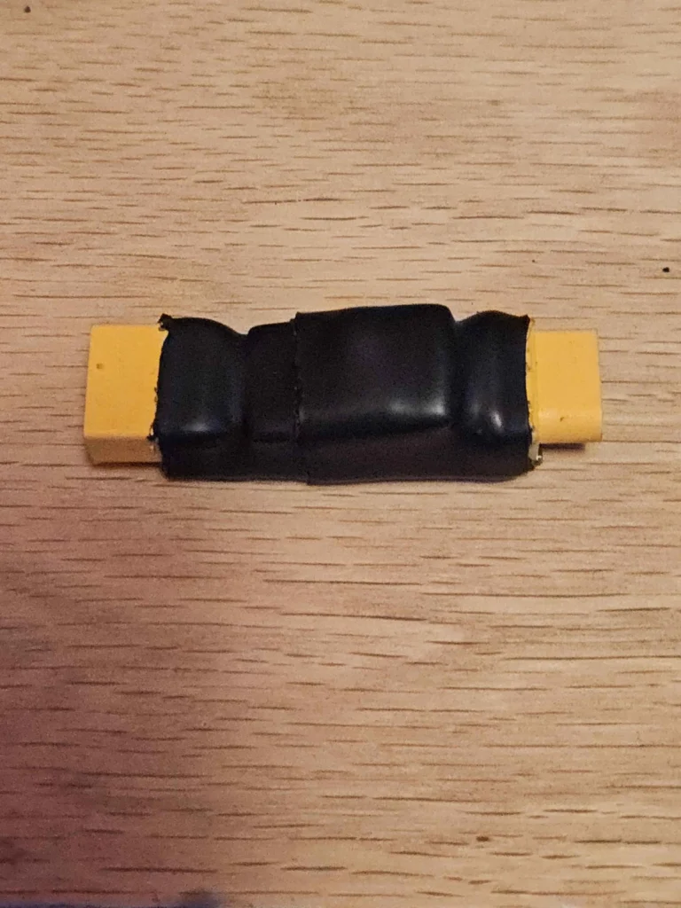
Module Assembly:
- The module fits directly between any DC power source and load. The final product shown here features XT60 connectors and heat-shrink insulation for safe, robust inline installation.
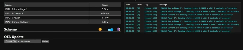
ESPHome & Home Assistant Integration:
- With default ESPHome YAML, the sensor publishes bus voltage, current, power, and shunt voltage readings. All values are accessible for automations and graphical dashboards in Home Assistant.


